Non-contact voltage tester: Make sure the power is off
1 of 6
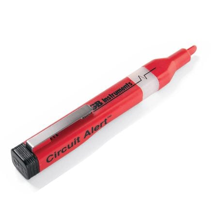
Non-contact voltage tester
This is the safest tool to confirm that electrical power is off, even before you touch a wire.
The two most important safety steps to take before opening any electrical box are:
Turn off the electrical power to that outlet at the main panel.
Double-check the outlet to make sure you turned off the right
circuit. A non-contact voltage tester is the best tool for this job.
With this tool, you don’t even have to touch a bare wire. The tester
will flash and/or chirp whenever it comes close to a hot wire. It’ll
even detect voltage (a hot wire) through the wire’s plastic insulation.
However, it’s not reliable when testing wires covered by metal conduit
or metal sheathing.
This tester is powered by small batteries, so make sure it works
before using it. Shove the tip into the slots of a receptacle that’s
live, hold it near a plugged-in lamp cord or hold it against a light
bulb that’s on. With most testers, you’ll see a series of flashes and
hear continuous chirps that indicate voltage. Testers may flash and
chirp at other times, but without the continuous pattern that indicates
a hot wire.
To test whether a receptacle is hot, simply shove the tester nose
into or against the plug slots (Photo 1). The hot slot is the smaller
of the two. However, you never know if the receptacle was wired
correctly, so it’s a good idea to test the neutral slot (the larger
one) too just in case the receptacle was wired wrong. And be sure to
check all the slots in the receptacle. Sometimes the lower set in a
duplex receptacle will be wired separately from the top. If a wall
switch controls the receptacle, make sure the switch is in the “on”
position.
Then unscrew the receptacle, carefully pull it out and test all the
wires again (Photo 2). At this point, you can shove the tester deeper
into the box to test wires not directly connected to the receptacle.
Several circuits may be present in a single box. We recommend that you
turn off all circuits to a box before working on it.
To test for power at a switch, you have to remove the cover plate
first. There’s usually enough space to poke the tester tip close to the
screw terminals (Photo 3). If there are no live wires, unscrew the
switch, pull it out and test all other wires in the box.
To test a light fixture before removing it, turn off the circuit at
the main panel, turn the light switch to “on,” remove the bulb and
poke the tester all the way down to the center socket button (Photo 4).
If the fixture is on a three-way switch (two switches), test with one
switch first in the up, then in the down position. If no voltage is
present, you can safely unscrew the fixture from the electrical box,
pull it out and test the other wires in the box as before.
The non-contact tester will also identify hot cables, even if
they’re covered by plastic insulation
This comes in handy
when you cut open a wall and find electrical cables and are unsure if
they are shut off.
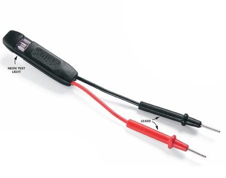
Circuit tester: Test for good grounding
The
two-lead circuit tester shown here also tests for voltage. When you
touch a live hot wire (black or any other color except green and white)
with one lead and a neutral (white) or ground (green or bare copper)
with the other, the neon test lamp should light (Photo 1). It confirms
that the power is on and that you have a complete (good) circuit. If
the light doesn’t come on, either the power is off or you have a bad
circuit.
This tool comes in especially handy in older homes when you want to
know if an equipment ground wire (green insulated or bare copper) is
actually connected to ground elsewhere in the system.
You often have to check this when you replace older ungrounded
switches with grounded ones as now required by the National Electrical
Code. You often find an unused bare ground wire folded back into the
box, and you have to test it to make sure that it’s connected to the
rest of the grounding system before hooking up your new switch.
To test a ground wire, follow these five steps:
Turn the power off to the switch (confirm with the non-contact
voltage tester) and uncap the neutral wires (they can remain in a
bundle).
Disconnect the two switch wires and spread the bare ends so they don’t touch one another (Photo 1).
Turn the power back on and identify the hot wire with the non-contact tester.
Confirm that the circuit tester is working by carefully touching the
hot wire with one lead and a neutral wire with the other. The tester
will light if it’s working.
Touch the hot wire with one lead and the ground wire with the other
(Photo 1). If the tester lights, the ground wire is good and you can
use it.
Follow a similar procedure when working with metal boxes in which no
ground wire comes into the box (Photo 2). In this case, you want to
find out whether the metal box itself is grounded (through conduit or
another method) and will therefore serve as the required ground.
With the wires separated and the power on, carefully touch the hot
wire with one lead and the metal box with the other. If the lamp
lights, you can use the metal box as a ground. If the lamp doesn’t
light, in most cases the NEC requires that you upgrade the box to have
some means of grounding before you install a receptacle, switch or
other device. Consult a licensed electrician or your local electrical
inspector for acceptable grounding methods.
Caution!
Avoid
touching a live hot wire and don't let it touch anything else. Hold the
tester leads by the insulated portion while making contact. And turn
the circuit off again as soon as you finish the test.
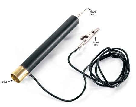
Continuity tester: Identify wires and test switches
It’s
difficult and dangerous to trace the routes of various wires with
circuits turned on. A continuity tester does it simply and safely with
the circuits turned off. It has a probe, which contains a battery and a
light bulb, and a wire lead. When you touch the ends to any continuous
conductive path, usually a wire, with both the probe and the lead, a
circuit will be complete and the bulb will light. In fact, to test the
bulb to make sure it’s working, simply touch the lead to the probe.
Working with several boxes and can’t remember which wire goes where?
With the power shut off, simply connect a test wire to a circuit wire
in one box (Photo 1), clip the lead to the test wire and touch the
probe to the ends of the circuit wires in the other box. The bulb will
light when you find the right wire.
Another great use for the circuit tester is to determine whether a switch is working (Photo 2).
Disconnect the switch, connect one lead to one terminal and put the
probe on the other while you flick the switch on and off. If the switch
is good, the bulb should light up and turn off as well.
Caution!
If
you have aluminum wiring, don't mess with it. Call in a licensed pro
who's certified to work with it. This wiring is dull gray, not the dull
orange that's characteristic of copper.
No comments:
Post a Comment